News
PRNU
04 November 2024
Photo Response Non-Uniformity (PRNU)
In an ideal world, each pixel in a digital image would accurately represent the light that entered the camera lens. In reality this is not the case due to imperfections in the capture process which result in the introduction of noise to the pixel value. Although there are different types of noise, the topic of this article will focus on pixel non-uniformity (PNU) and the manner in which it can be utilised in imagery authentication examinations.

Figure 1: A micrograph of the corner of the photosensor array of a webcam digital camera
A camera sensor is essentially an array of cells, each of which contains a photodetector. These photodetectors convert photons (or light) to an electron (or an electrical signal). The electrons are then converted to an integer to represent a single pixel within a digital image (Vlado Damjanovski, 2014). When photodetectors are manufactured, each has slightly different physical properties to the next, owed to the variance in the silicon wafer sensors construction and the varying dimensions of such. This results in some of the detectors underrepresenting the amount of light that they receive (and thus underrepresenting the associated pixel value) and others over representing it. This variability is consistent regardless of the scene captured. When the array of photodetectors pertaining to a camera sensor is considered in its entirety, a stable pattern is established. The combination of slight but consistent variations in the photodetectors and their configuration within a camera forms patterns which can be considered extremely rare, if not unique for each camera sensor. The premise for the method being discussed in this blog is that each camera, regardless of whether they are within a set consisting of only the same model, will therefore have a unique pattern (Hany Farid, 2016).
The rare and consistent nature of the pattern can be taken advantage of for the purposes of imagery authentication through a method first proposed by (Lukáš, et al., 2006). This can be deconstructed into the following three stages.
First, the PRNU pattern (abbreviated from photo response non-uniformity) is estimated from a source camera or set of cameras. This is achieved by capturing multiple images, preferably of a scene in which the light values are similar, such as a uniform wall or the sky. Each of these images is then de-noised, and the de-noised versions are subtracted from the original images to give residual noise values. These noise values are then averaged. In order for the method to be effective is essential that all images used have the same resolution, orientation and quality to ensure each sensor responds to the same pixel value.
Second, the PRNU is estimated from an evidence image through the same process – de-noising followed by subtraction from the original image to provide a residual noise value. It should be noted that clipped imagery cannot be used as it will obscure the PRNU due to the saturation of the pixel values. Heavily compressed images (50% or higher) will also distort the PRNU, so they should not be used.
Third, the correlation between the PRNU pattern relating to the source camera and that relating to the evidence image is calculated. If the resulting correlation exceeds a pre-defined threshold, it is proposed that the camera is the source of the evidence image (Goljan et al., 2009). This threshold can be determined in a variety of ways, all of which are based on the value relative to that of a dataset.
In performing the method described above, a source device can be attributed to a specific source, and localised image tampering can be detected as there will be a region or regions in which the pattern is not congruent with the pattern relating to the source device.
Limitations
In order for the method to be applied, the purported source must first be available for reference images to be captured and the camera sensor's PRNU pattern subsequently extracted. If this is possible, then care must be taken to ensure the images are not subject to clipping and that they have not been subject to cropping, rescaling rotation or digital zoom, as all will corrupt the PSNR pattern. As transcoding an image will convert the pixels and thus manipulate the original PRNU pattern, the chain of custody of the evidence image must also be considered, as the method should only be applied to images purported to be original or digital bit-stream copies of such.
Recent research has also found that newer mobile devices use multiple camera lenses to capture digital images and apply a degree of processing that impacts the pixel values. Thus, as with all methods, validation exercises should be performed prior to method implementation to determine the limitations of such (Iuliani et al., 2021).
Mandet Implementation
The extraction of the PRNU pattern and subsequent comparison to an evidence image is implemented in a ‘wizard’ format to guide the user through all the steps of the process. The process can be started from the main menu option Ballistics -> PRNU Camera (Figure 2).

Figure 2: Start point of the PRNU measurement for an evidence image.
The first step of the process is to load the reference images taken with the device of interest. In Figure 3a you see the wizard and in Figure 3b examples of the reference images.

Figure 3: a. Loading the reference images to calculate the signature of the device of interest and b. Examples of these images.
Now the device of interest (DOI) signature can be calculated from a substantial number of reference images. These images can be created by taking pictures of a grey wall to suppress the contributions from the specific image contents. Subsequently a signature must be calculated from the image of interest (IOI, see Figure 4).
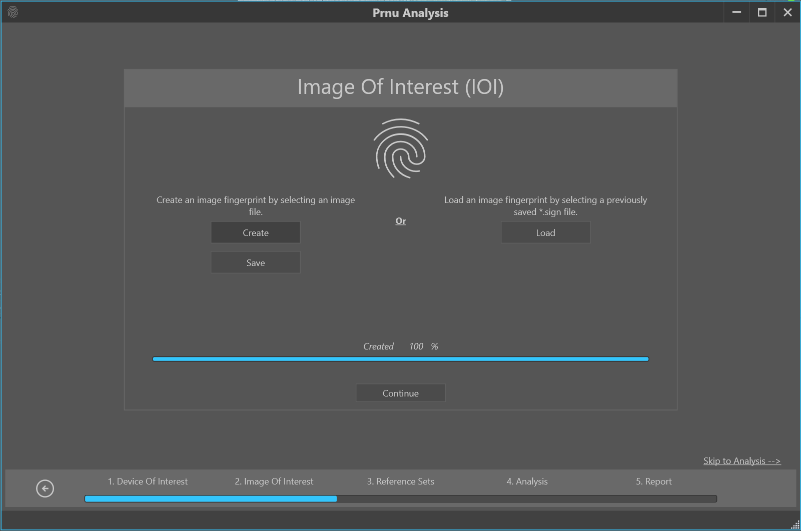
Figure 4: Calculating the signature of the image of interest (IOI).
A further requirement is a set of other images captured with the same camera, the so-called Device Set (see Figure 5) and a larger set of random images that natively have the same dimensions but are NOT taken by the same camera – referred to as the Random Set.
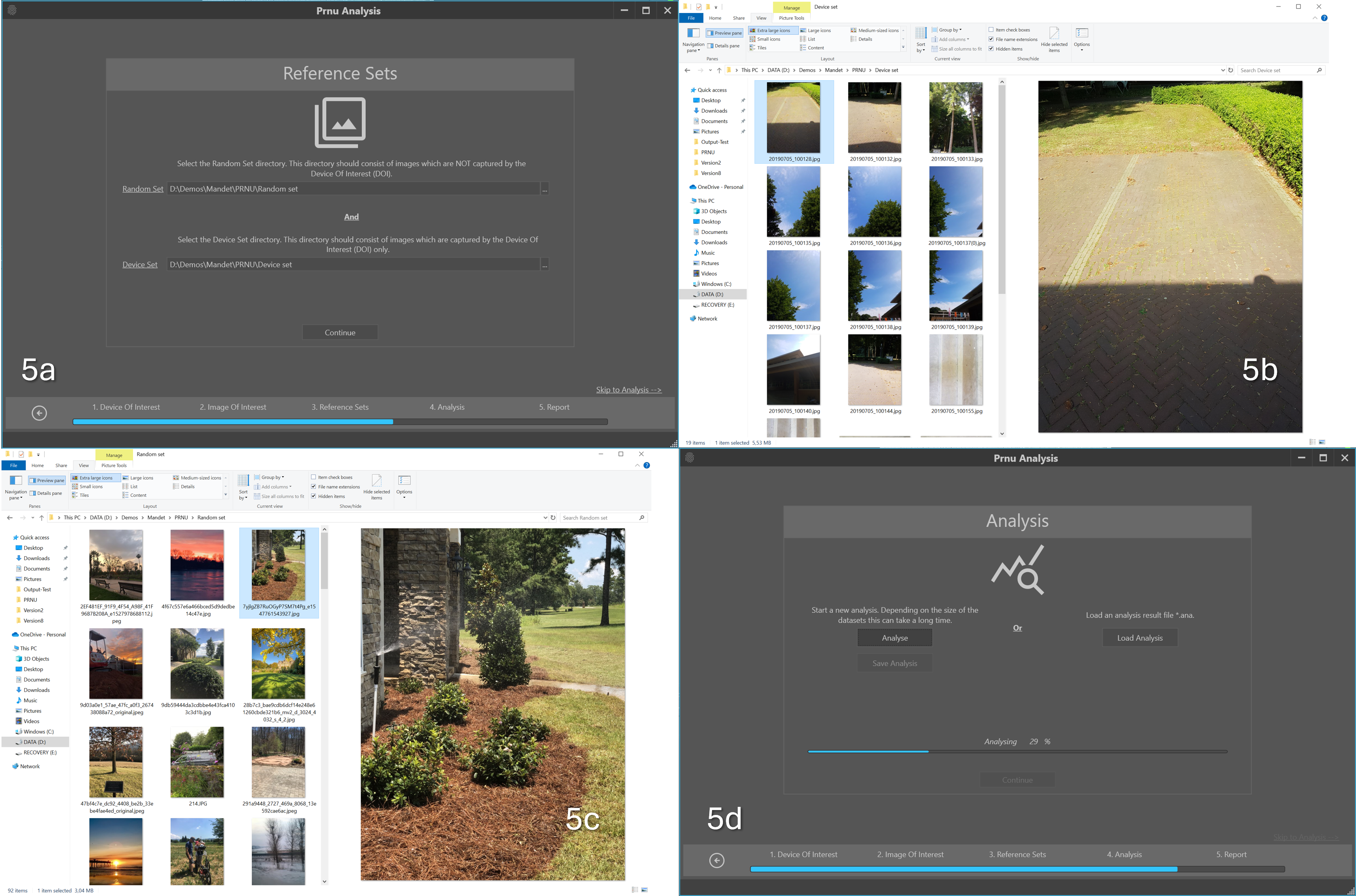
Figure 5: a. selecting the Random Set and Device Sets needed as references for the measurement, b. examples of the device set images taken by the same camera c. random images of the same dimensions NOT taken by the same camera and d. performing the matching between image and camera.
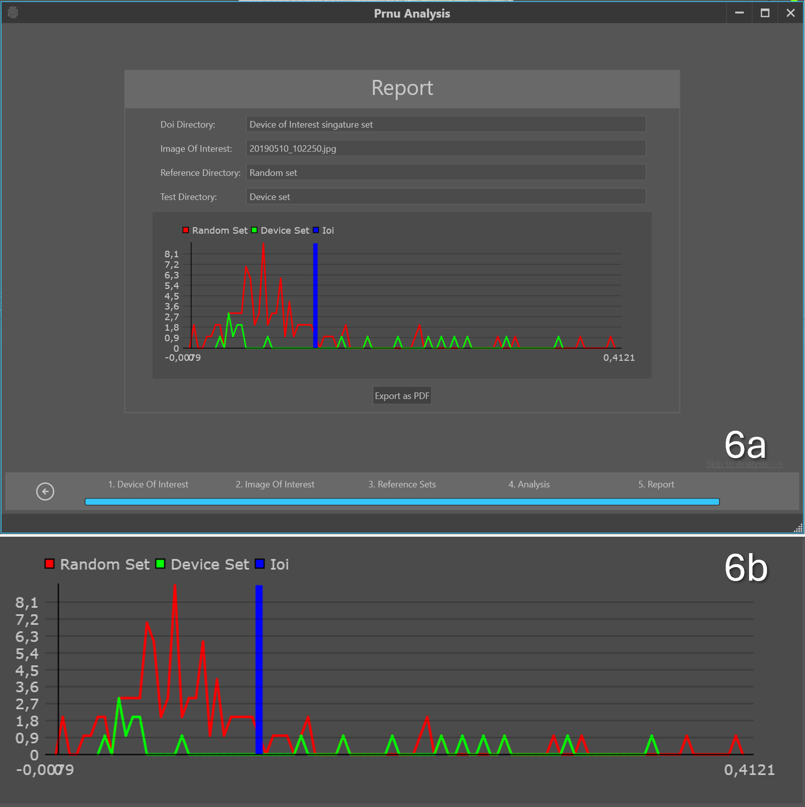
Figure 6: a. result of the analysis and b. closeup of the plot.
The results are presented in a plot that can be exported as a PRNU report in PDF-file format. The plot in Figure 6 shows the comparison of the PRNU signature concerning the image of interest versus the camera (blue line), the camera versus the random set (red line) and the device set versus camera (green line).
If the blue line is to the right of the main peak of the red line, it indicates that the similarity of the PRNU signals is higher between the image of interest and the device of interest than the device of interest and a random set of images. If the blue line is inside the range of the device set, extra support is given to this finding.
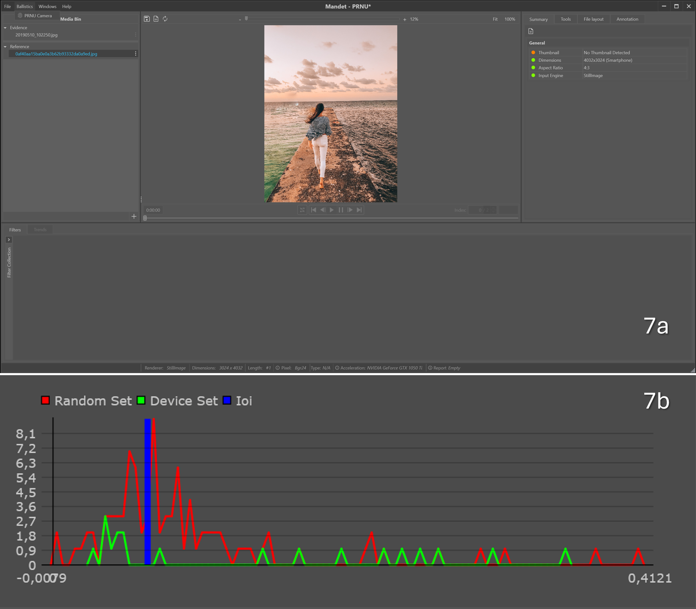
Figure 7: a. performing the same analysis with an image that was NOT captured by the same camera and b. the resulting plot show an image of interest that coincides with the main peak of the random set.
Another measurement was made with identical data, changing only the image of interest to an image that was NOT captured by the camera but with identical dimensions (see Figure 7). The signal from the image of interest coincided with the signal from the random set. This supports the conclusion that the image was NOT taken by the camera.
Conclusion
PRNU is a robust method that has been the subject of a number of published articles and is thus has scientific foundations. It is a valuable method for both attribution of source and local tampering detection, but in order to be employed a number of criteria must be met – not least the availability of the purported camera or reference imagery obtained using such and its application only to devices that utilise a single camera lens when capturing a single image. When it can be employed, its probative value can be considered extremely high, so where possible, efforts should be made to ensure the criteria are met.
References
Goljan, M., Fridrich, J., Filler, T., 2009. Large scale test of sensor fingerprint camera identification, in: Delp III, E.J., Dittmann, J., Memon, N.D., Wong, P.W. (Eds.), . Presented at the IS&T/SPIE Electronic Imaging, San Jose, CA, p. 72540I. https://doi.org/10.1117/12.805...
Hany Farid, 2016. Photo Forensics. MIT Press, London.
Iuliani, M., Fontani, M., Piva, A., 2021. A Leak in PRNU Based Source Identification—Questioning Fingerprint Uniqueness 9.
Lukáš, J., Fridrich, J., Goljan, M., 2006. Digital Camera Identification From Sensor Pattern Noise. IEEE Trans. Inf. Forensics Secur. 1, 205–214. https://doi.org/10.1109/TIFS.2...
Vlado Damjanovski, 2014. CCTV: From light to pixels, 3rd Edition. ed. Elsevier.
