News
Re-scaling
05 October 2020
Article by James Zjalic (Verden Forensics) and Foclar
Problem
When reviewing digital imagery, the scale of such presented to the user can make it difficult for interpretation, especially if in cases where the pertinent object or region is at a distance from the camera lens. This can affect both examiners and end-users a like, and while an examiner has control over any effects that increasing the size may have through the use of validated software, the end-user will likely increase the size of any imagery to fit their computer monitor and apply magnification without understanding the impact of such on the content.
Re-scaling is an operation used to change the size and sometimes the orientation of digital imagery to aid in interpretation [1].
Cause
The need for resampling essentially stems from the inability of the eye to reliably interpret regions within digital imagery due to the size. The reason for small features generally fits into one of three categories:
- The resolution of the imagery is poor.
- Where the resolution is low, the representation of regions within will also be low, and as such, the features will be difficult to interpret.
- The region of interest is at a distance from the camera lens.
- Although the resolution of the overall capture may be good, the number of pixels used to represent the region is low due to the distance of such from the camera lens.
- The region of interest is captured at an unnatural orientation
On occasion, features can be captured from a perspective which is inconsistent with that expected, for example, a vehicle captured at a 90o orientation which is therefore displayed vertically rather than horizontally.
Re-scaling of the imagery is of paramount importance to allow a reliable judgement to be made, as the quality of the content can become both easier to view, and artefacts caused by pixel boundary edges can appear reduced. With that being said, caution must be taken as any re-scaling operation which increases the size or rotates the imagery on a non 90o axis can only result in a reduction in the information within an image. Re-sampling cannot increase the resolution of a region, or the information within, as the data has not been captured in the first place.
Theory
Re-scaling (or resampling) is the process of transforming a discrete image to a new set of coordinates through interpolation (the use of known data to estimate values at unknown locations) [2].
There are a variety of interpolation algorithms available, and the selection of such is highly dependent on the application. All re-scaling processes are based on two general steps:
- The interpolation of a discrete image to a continuous image;
- The sampling of the interpolation image to the new grid.
The most commonly known types of interpolation [3], [4] used for image re-scaling can be categorised based on the number of known data values used to estimate each new values, as follows:
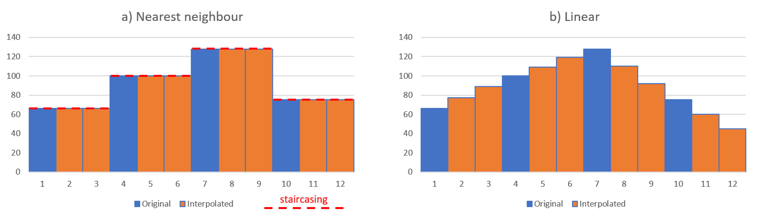
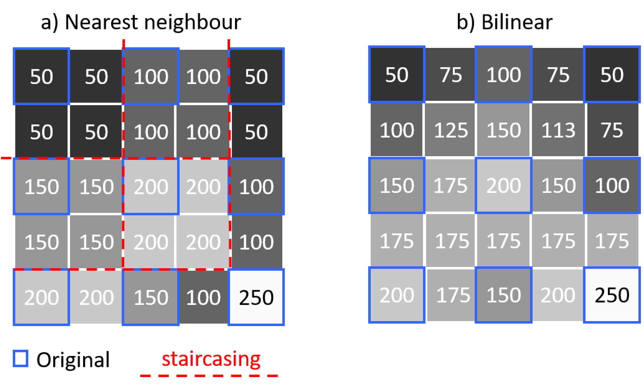
Nearest Neighbour – Uses a single value, where the value of the new pixel is taken from the value of the nearest existing pixel. For one- and two-dimensional examples see Figure 1a and Figure 2a.
Linear – Uses two values either side of the new pixel (see Figure 1b), where the value of the new pixel is taken from the mean of the values of the existing pixels.
Bilinear – Uses four values by implementing linear interpolation on both the horizontal and vertical axis (see Figure 2b).
Bicubic – Uses the sixteen nearest pixels by using the four-pixel values at each of the corners of the pixel, as well as the four-pixel values at each of those pixels corners.
Solution
One of the core principles of forensics is to maintain the integrity of evidence [5], and this should be taken into account for all processes from capture to processing. In light of this, several of the interpolation methods must be used with extreme caution, and as the type of interpolation can change the content in different ways, the type used should always be documented within working notes and the final report to ensure reproducibility and transparency. For instance, if one examiner uses bicubic interpolation and other nearest neighbour, the new pixels introduced in each will vary, opening up the potential for differences in interpretation of the same source imagery. With that being said, the algorithm used is of less concern when the imagery is for presentational purposes only, such as when using markers to indicate the movement of a subject within an environment.
As nearest neighbour uses the values of pixels already with the environment rather than create new values from the mean of surrounding pixels, this is the safest option for any imagery which will be used for interpretive purposes. The disadvantage is the staircasing (see red dotted lines in Figures 1 and 2) effect it can have on edges due to the coarse disparity between neighbouring pixels, and the shift in the position of pixel locations. For example, if the locations of new pixels are halfway between the existing pixels, the image will be shifted by half a pixel. Best practice is to resample to a coordinate system with sample spacing that is an integer factor of the original, so the resampled data reproduces the original image.
Implementations
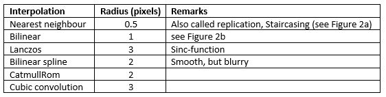
Interpolation techniques use different mathematical functions to interpolate the pixel values, and as such, the number of neighbouring pixels that are used to calculate the result value differ. The local neighbourhood used to calculate the interpolated value can be characterised by a pixel radius. The interpolation techniques for scaling available in Impress [6] are listed in Table 1.
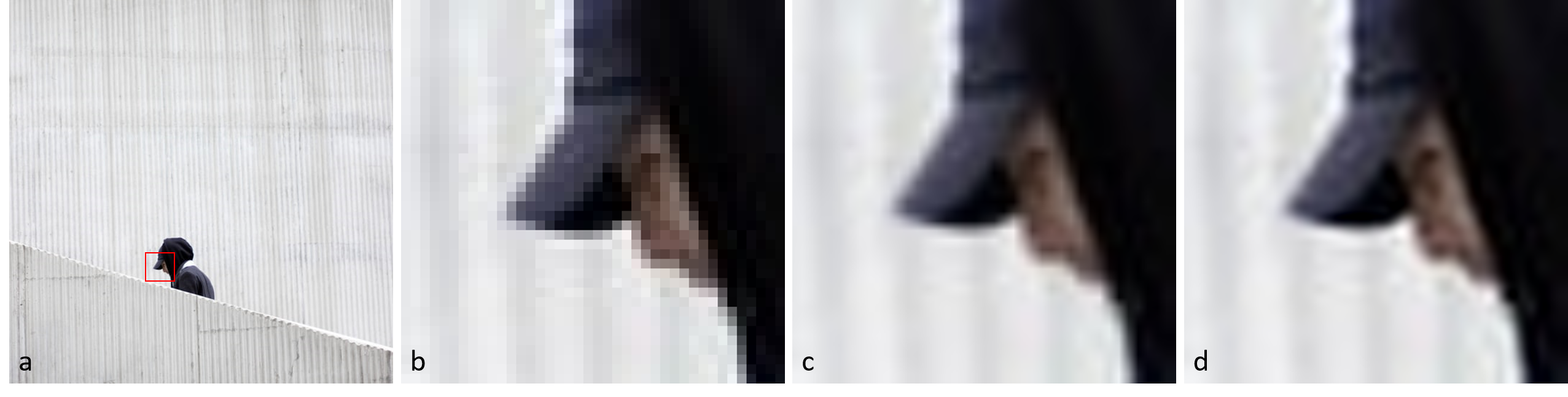
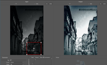
Multiple interpolation techniques are added because of the different characteristics of the resulting images. In Figure 3 an example is shown of three interpolation techniques. From the image it becomes clear that different techniques can produce images of varying degrees of smoothness. Depending on the image content and personal preference a specific technique can be selected.
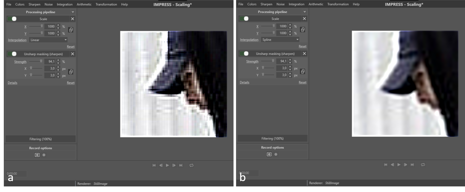
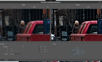
The blurriness introduced by the scaling can be compensated by using a sharpen filter after the scaling. Care should be taken to select the right interpolation and the strength of the applied sharpening. Figure 4 shows an example of combining scaling and sharpening. The strong sharpening starts to emphasise artefacts introduced by the interpolation in case of bicubic spline (Figure 4b). In case of bilinear interpolation (Figure 4a), using the same sharpening, the result is much worse.
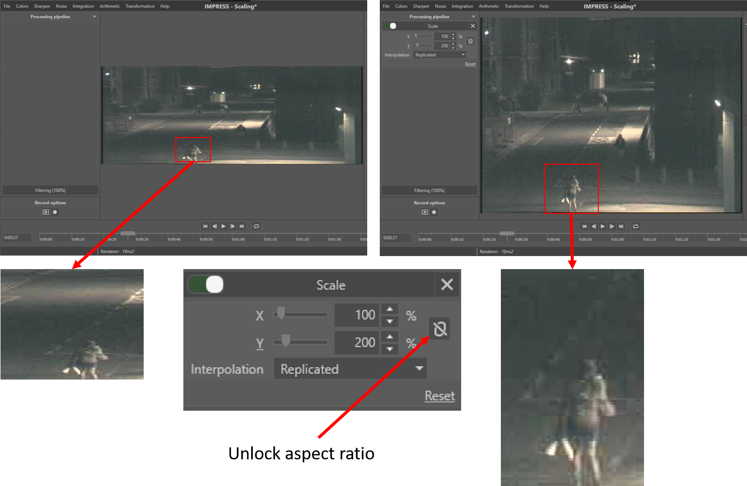
The aspect ratio of an image is the ratio of width and height (width / height). In some cases an image do not give a good representation of objects from the real world in the image, because the aspect ratio is incorrect (see Fig.5). This can be the result of the recording technique or partially corrupt image data. The scaling filter can be used to adjust the image dimensions to better fit the real world aspect ratio. The operator has to unlock the aspect ratio (Fig. 5), in which case the horizontal and vertical scaling factor can be set independently.
Conclusion
Prior to selecting an interpolation algorithm, the application of the final product should be considered, and a decision made on the impact of the processing on the final interpretation. For tasks which require interpretation, it is always best to urge on the side of caution and use nearest neighbour to ensure no new information is generated and added to the image, but for presentational purposes, the selection is of less concern.
References
[1] N. A. Dodgson, “Image resampling,” University of Cambridge, Cambridge, UK, 1992.
[2] Rafael C. Gonzalez and Richard E. Woods, Digital Image Processing, 3rd Edition. Pearson, 2007.
[3] A. Suwendi and J. P. Allebach, “Nearest-neighbor and bilinear resampling factor estimation to detect blockiness or blurriness of an image,” J. Electron. Imaging, vol. 17, p. 16.
[4] J. Anthony Parker, Robert V. Kenyon, and Donald E. Troxel, “Comparison of Interpolating Methods for Image Re-sampling,” IEEE Trans. Med. Imag., no. 1, Mar. 1983.
[5] ACPO, “ACPO Good practice guide for digital evidence,” Mar. 2012.
[6] Bovik Alan C. Handbook of Image and Video Processing, p33 Academic Press (2010).